DPVS-FullNAT模式管理篇

本文最后更新于:August 10, 2021 pm

本文主要介绍基于CentOS7.9系统部署DPVS的FullNAT模式的各种部署方式和配置管理,包括IPv4-IPv4、bonding、IPv6-IPv6、IPv6-IPv4(NAT64)和keepalived模式这五种方案。

以下的配置全部基于双臂模式,并且RS机器上面已经安装了DPVS相应的toa模块。我们先从单个网卡的IPv4简单配置开始,接着再做bonding配置,然后再进行IPv6简单配置,NAT64配置以及最后使用keepalived配置主备模式。

本文中安装的DPVS版本为1.8-10,dpdk版本为18.11.2,详细安装过程已在之前的文章DPVS-FullNAT模式部署篇 - TinyChen’s Studio中叙述过,这里不做赘述。

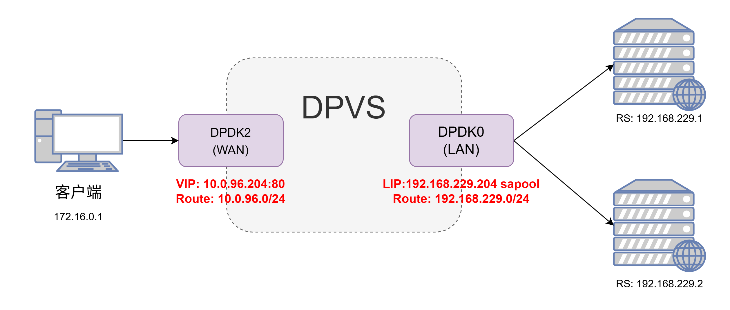
1、IPv4简单配置

1.1 架构图

首先是最简单的配置方式,直接使用ipvsadm的命令行操作来实现一个IPv4网络的FullNat模式,架构图如下:

这里我们使用dpdk2网卡作为wan口,dpdk0网卡作为lan口

1.2 配置过程

1
2
3
4
5
6
7
8
9
10
11
12
13
14
15
16
17
18
19
20
21
22
23
24
25
26
27
28
29
30
31
32
33
34
35
36
37
38
39
40
41
42
43
44
45
46
47
# 首先我们把VIP 10.0.96.204 加到dpdk2网卡(wan)上
$ dpip addr add 10.0.96.204/32 dev dpdk2

# 接着我们需要添加两条路由,分为是wan口网段的路由和到RS机器网段的路由
$ dpip route add 10.0.96.0/24 dev dpdk2
$ dpip route add 192.168.229.0/24 dev dpdk0
# 最好再加一条到网关的默认路由保证ICMP数据包的回包能跑通
$ dpip route add default via 10.0.96.254 dev dpdk2

# 使用RR算法建立转发规则
# add service <VIP:vport> to forwarding, scheduling mode is RR.
# use ipvsadm --help for more info.
$ ipvsadm -A -t 10.0.96.204:80 -s rr

# 这里为了方便测试我们只添加一台RS
# add two RS for service, forwarding mode is FNAT (-b)
$ ipvsadm -a -t 10.0.96.204:80 -r 192.168.229.1 -b

# 添加LocalIP到网络中,FNAT模式这里需要
# add at least one Local-IP (LIP) for FNAT on LAN interface
$ ipvsadm --add-laddr -z 192.168.229.204 -t 10.0.96.204:80 -F dpdk0


# 然后我们查看一下效果
$ dpip route show
inet 192.168.229.204/32 via 0.0.0.0 src 0.0.0.0 dev dpdk0 mtu 1500 tos 0 scope host metric 0 proto auto
inet 10.0.96.204/32 via 0.0.0.0 src 0.0.0.0 dev dpdk2 mtu 1500 tos 0 scope host metric 0 proto auto
inet 10.0.96.0/24 via 0.0.0.0 src 0.0.0.0 dev dpdk2 mtu 1500 tos 0 scope link metric 0 proto auto
inet 192.168.229.0/24 via 0.0.0.0 src 0.0.0.0 dev dpdk0 mtu 1500 tos 0 scope link metric 0 proto auto
inet 0.0.0.0/0 via 10.0.96.254 src 0.0.0.0 dev dpdk2 mtu 1500 tos 0 scope global metric 0 proto auto

$ dpip addr show
inet 10.0.96.204/32 scope global dpdk2
valid_lft forever preferred_lft forever
inet 192.168.229.204/32 scope global dpdk0
valid_lft forever preferred_lft forever

$ ipvsadm -ln
IP Virtual Server version 0.0.0 (size=0)
Prot LocalAddress:Port Scheduler Flags
-> RemoteAddress:Port Forward Weight ActiveConn InActConn
TCP 10.0.96.204:80 rr
-> 192.168.229.1:80 FullNat 1 0 0
$ ipvsadm -G
VIP:VPORT TOTAL SNAT_IP CONFLICTS CONNS
10.0.96.204:80 1
192.168.229.204 0 0

然后我们在RS上面启动一个nginx,设置返回IP和端口号,然后直接对VIP使用ping和curl命令进行测试:

1
2
3
4
5
6
7
8
9
10
11
12
13
$ ping -c4 10.0.96.204
PING 10.0.96.204 (10.0.96.204) 56(84) bytes of data.
64 bytes from 10.0.96.204: icmp_seq=1 ttl=54 time=47.2 ms
64 bytes from 10.0.96.204: icmp_seq=2 ttl=54 time=48.10 ms
64 bytes from 10.0.96.204: icmp_seq=3 ttl=54 time=48.5 ms
64 bytes from 10.0.96.204: icmp_seq=4 ttl=54 time=48.5 ms

--- 10.0.96.204 ping statistics ---
4 packets transmitted, 4 received, 0% packet loss, time 8ms
rtt min/avg/max/mdev = 47.235/48.311/48.969/0.684 ms

$ curl 10.0.96.204
Your IP and port is 172.16.0.1:62844

1.3 小结

该模式非常的简单,可以快速配置检验自己机器上的DPVS能否正常工作,不过由于是单点,往往较少使用。
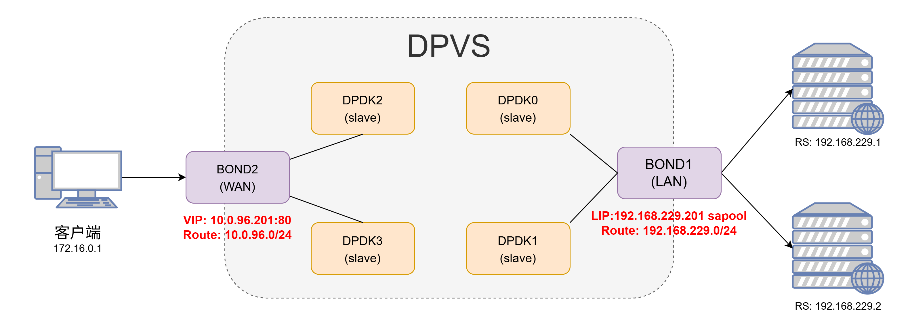
2、bonding配置

目前DPVS支持配置bonding4bonding0,两者的配置基本相同,配置方式可以参考dpvs/conf/dpvs.conf.single-bond.sample这个文件。

配置bonding模式的时候,不需要对slave网卡(如dpdk0等)指定kni_name这个参数,而是要在bonding中指定对应的kni_name,同时还要注意primary参数指定的网卡的MAC地址一般就是bonding网卡的MAC地址。

1
2
3
4
5
6
7
8
9
10
11
12
13
14
15
16
17
18
19
20
21
22
23
24
25
26
27
28
29
30
31
32
33
34
35
36
37
38
39
40
41
42
43
44
45
46
47
48
49
50
51
52
53
54
55
56
57
58
59
60
61
62
63
64
65
66
67
68
69
70
71
72
73
74
75
76
77
78
79
80
81
82
83
84
85
86
87
88
89
90
91
92
93
94
95
96
97
98
99
100
101
102
103
104
105
106
107
108
109
! netif config
netif_defs {
<init> pktpool_size 1048575
<init> pktpool_cache 256

<init> device dpdk0 {
rx {
max_burst_size 32
queue_number 16
descriptor_number 1024
rss all
}
tx {
max_burst_size 32
queue_number 16
descriptor_number 1024
}
fdir {
mode perfect
pballoc 64k
status matched
}
! mtu 1500
! promisc_mode
! kni_name dpdk0.kni
}

<init> device dpdk1 {
rx {
max_burst_size 32
queue_number 16
descriptor_number 1024
rss all
}
tx {
max_burst_size 32
queue_number 16
descriptor_number 1024
}
fdir {
mode perfect
pballoc 64k
status matched
}
! mtu 1500
! promisc_mode
! kni_name dpdk1.kni
}

<init> device dpdk2 {
rx {
max_burst_size 32
queue_number 16
descriptor_number 1024
rss all
}
tx {
max_burst_size 32
queue_number 16
descriptor_number 1024
}
fdir {
mode perfect
pballoc 64k
status matched
}
! mtu 1500
! promisc_mode
! kni_name dpdk2.kni
}

<init> device dpdk3 {
rx {
max_burst_size 32
queue_number 16
descriptor_number 1024
rss all
}
tx {
max_burst_size 32
queue_number 16
descriptor_number 1024
}
fdir {
mode perfect
pballoc 64k
status matched
}
! mtu 1500
! promisc_mode
! kni_name dpdk3.kni
}

<init> bonding bond1 {
mode 4
slave dpdk0
slave dpdk1
primary dpdk0
kni_name bond1.kni
}

<init> bonding bond2 {
mode 4
slave dpdk2
slave dpdk3
primary dpdk2
kni_name bond2.kni
}
}

随后在配置每个worker-cpu的时候要注意port要选择对应的bond网卡

1
2
3
4
5
6
7
8
9
10
11
12
<init> worker cpu1 {
type slave
cpu_id 1
port bond1 {
rx_queue_ids 0
tx_queue_ids 0
}
port bond2 {
rx_queue_ids 0
tx_queue_ids 0
}
}

DPVS的bonding配置和在Linux中直接操作一样。bonding配置成功后只需要对生成的bonding网卡操作即可,使用dpip命令可以查看对应网卡的工作状态:如下面的网卡就工作在全双工、20000 Mbps速率的模式下,MTU为1500,并且在DPVS中配置了16个收发队列。

1
2
3
4
5
6
7
$ dpip link show
5: bond1: socket 0 mtu 1500 rx-queue 15 tx-queue 16
UP 20000 Mbps full-duplex auto-nego
addr AA:BB:CC:11:22:33
6: bond2: socket 0 mtu 1500 rx-queue 15 tx-queue 16
UP 20000 Mbps full-duplex auto-nego
addr AA:BB:CC:12:34:56

3、IPv6简单配置

3.1 DPVS配置过程

IPv6的简单配置方法和IPv4一样,只是把对应的IPv4地址换成了IPv6地址,同时还需要额外注意一下IPv6地址指定端口的时候需要使用[]将IP地址括起来。

1
2
3
4
5
6
7
8
9
10
11
12
13
14
15
16
17
18
19
20
21
22
23
24
25
26
27
28
29
30
31
32
33
34
35
36
# 添加VIP和相关路由
$ dpip addr add 2001::201/128 dev bond2
$ dpip route -6 add 2001::/64 dev bond2
$ dpip route -6 add 2407::/64 dev bond1
$ dpip route -6 add default via 2001::1 dev bond2

# 配置ipvsadm和RS
$ ipvsadm -A -t [2001::201]:80 -s rr
$ ipvsadm -a -t [2001::201]:80 -r [2407::1]:80 -b
$ ipvsadm -a -t [2001::201]:80 -r [2407::2]:80 -b
# 添加IPv6 LIP
$ ipvsadm --add-laddr -z 2407::201 -t [2001::201]:80 -F bond1


$ dpip addr show
inet6 2407::201/128 scope global bond1
valid_lft forever preferred_lft forever
inet6 2001::201/128 scope global bond2
valid_lft forever preferred_lft forever


$ dpip route -6 show
inet6 2001::201/128 dev bond2 mtu 1500 scope host
inet6 2407::201/128 dev bond1 mtu 1500 scope host
inet6 2407::/64 dev bond1 mtu 1500 scope link
inet6 2001::/64 dev bond2 mtu 1500 scope link
inet6 default via 2001::1 dev bond2 mtu 1500 scope global

$ ipvsadm -Ln
IP Virtual Server version 0.0.0 (size=0)
Prot LocalAddress:Port Scheduler Flags
-> RemoteAddress:Port Forward Weight ActiveConn InActConn
TCP [2001::201]:80 rr
-> [2407::1]:80 FullNat 1 0 0
-> [2407::2]:80 FullNat 1 0 0

3.2 效果检验

测试效果,确认RS上面的nginx能够正常返回用户端的真实IP和端口,则表明配置正常。

1
2
$  curl -6 "http://\[2001::201\]"
Your IP and port is [2408::1]:38383

4、NAT64配置

4.1 DPVS配置过程

架构图上和之前的两个并没太大的不同,只是IP略有差异

1
2
3
4
5
6
7
8
9
10
11
12
13
14
15
16
17
18
19
20
21
22
23
24
25
26
27
28
29
30
31
32
33
34
35
36
37
# 添加VIP和相关路由
$ dpip addr add 2001::201/128 dev bond2
$ dpip route -6 add 2001::/64 dev bond2
$ dpip route add 192.168.229.0/23 dev bond1
$ dpip route -6 add default via 2001::1 dev bond2

# 配置ipvsadm和RS
$ ipvsadm -A -t [2001::201]:80 -s rr
$ ipvsadm -a -t [2001::201]:80 -r 192.168.229.1:80 -b
$ ipvsadm -a -t [2001::201]:80 -r 192.168.229.2:80 -b
# 添加IPv6 LIP
$ ipvsadm --add-laddr -z 192.168.229.201 -t [2001::201]:80 -F bond1


$ dpip addr show
inet6 2001::201/128 scope global bond2
valid_lft forever preferred_lft forever
inet 192.168.229.201/32 scope global bond1
valid_lft forever preferred_lft forever

$ dpip route show
inet 192.168.229.201/32 via 0.0.0.0 src 0.0.0.0 dev bond1 mtu 1500 tos 0 scope host metric 0 proto auto
inet 192.168.229.0/23 via 0.0.0.0 src 0.0.0.0 dev bond1 mtu 1500 tos 0 scope link metric 0 proto auto

$ dpip route -6 show
inet6 2001::201/128 dev bond2 mtu 1500 scope host
inet6 2001::/64 dev bond2 mtu 1500 scope link
inet6 default via 2001::1 dev bond2 mtu 1500 scope global

$ ipvsadm -ln
IP Virtual Server version 0.0.0 (size=0)
Prot LocalAddress:Port Scheduler Flags
-> RemoteAddress:Port Forward Weight ActiveConn InActConn
TCP [2001::201]:80 rr
-> 192.168.229.1:80 FullNat 1 0 0
-> 192.168.229.2:80 FullNat 1 0 0

测试效果

1
2
$  curl -6 "http://\[2001::201\]"
Your IP and port is 192.168.229.201:1035

从上面的测试结果来看,即使是安装了TOA模块,也无法获取NAT64模式下客户端的源IP地址,所有的客户端IP和端口都会变成LIP转发过来的时候的IP和端口。如果是对源IP没需求的话可以忽略这个问题,如果有需求的话则需要更改RS上面的客户端程序,下面我们以nginx为例。

4.2 NGINX支持NAT64

dpvs还为nginx提供了一个nat64的toa模块,当VIP为ipv6而RS为ipv4的时候,可以使用这个模块在nginx中获取用户真实的ipv6地址,需要我们在源码编译安装nginx之前先打上这个补丁。

从官方的文件名我们可以看出应该是基于1.14.0版本制作的patch,首先我们使用旧版的1.14.0版本能够正常打上补丁,后续的编译安装也能正常进行

1
2
3
4
5
6
7
8
9
10
$ pwd
/home/nginx-1.14.0
$ ls
auto CHANGES CHANGES.ru conf configure contrib html LICENSE man nginx-1.14.0-nat64-toa.patch README src
$ cp /home/dpvs/kmod/toa/example_nat64/nginx/nginx-1.14.0-nat64-toa.patch ./
$ patch -p 1 < nginx-1.14.0-nat64-toa.patch
patching file src/core/ngx_connection.h
patching file src/core/ngx_inet.h
patching file src/event/ngx_event_accept.c
patching file src/http/ngx_http_variables.c

使用最新的nginx-1.21.1版本的时候会有报错

1
2
3
4
5
6
7
8
9
10
11
12
13
14
15
16
17
18
19
20
$ cp /home/dpvs/kmod/toa/example_nat64/nginx/nginx-1.14.0-nat64-toa.patch ./
$ pwd
/home/nginx-1.21.1
$ ls
auto CHANGES CHANGES.ru conf configure contrib html LICENSE man nginx-1.14.0-nat64-toa.patch README src

$ patch -p 1 < nginx-1.14.0-nat64-toa.patch
patching file src/core/ngx_connection.h
Hunk #1 FAILED at 144.
1 out of 1 hunk FAILED -- saving rejects to file src/core/ngx_connection.h.rej
patching file src/core/ngx_inet.h
Hunk #1 succeeded at 128 with fuzz 2 (offset 2 lines).
patching file src/event/ngx_event_accept.c
Hunk #1 succeeded at 17 (offset -5 lines).
Hunk #2 succeeded at 30 (offset -5 lines).
Hunk #3 succeeded at 172 (offset -5 lines).
patching file src/http/ngx_http_variables.c
Hunk #1 succeeded at 145 (offset 2 lines).
Hunk #2 succeeded at 398 (offset 15 lines).
Hunk #3 succeeded at 1311 (offset -11 lines).

仔细查看patch文件内容可以发现出现错误是因为1.21.1版本中对应部分移除了几行代码导致patch无法匹配,我们手动将那一行代码加上去

随后就能正常编译安装了,完成之后我们可以在日志中加入$toa_remote_addr$toa_remote_port这两个变量来获取NAT64模式下的客户端真实IP。

4.3 效果检验

再次测试发现能够显示真正的客户端源IP地址和端口号。

1
2
3
4
5
6
$  curl -6 "http://\[2001::201\]"
Your remote_addr and remote_port is 192.168.229.201:1030
Your toa_remote_addr and toa_remote_port is [2408::1]:64920

# 同时在nginx的日志中也能看到对应的字段
toa_remote_addr=2408::1 | toa_remote_port=64920 | remote_addr=192.168.229.201 | remote_port=1030

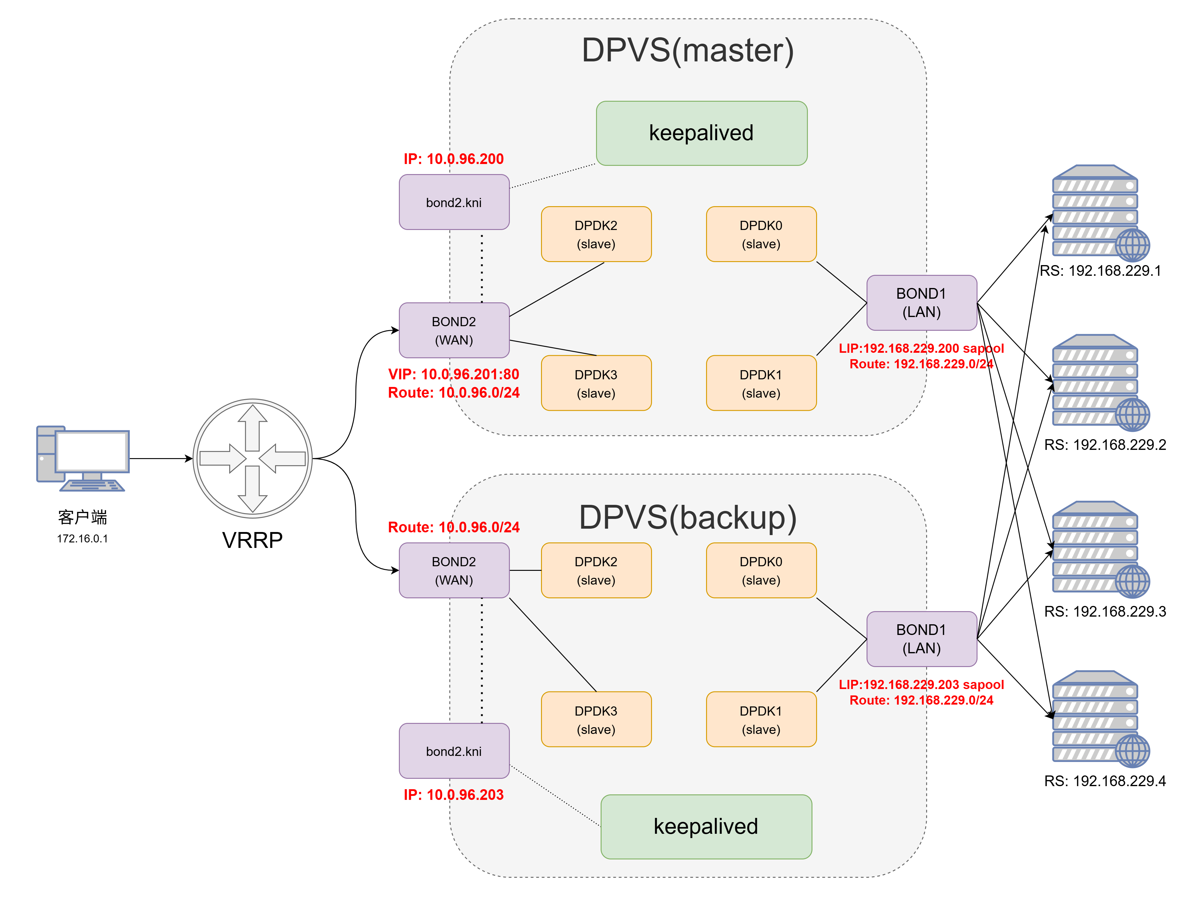
5、keepalived配置

5.1 架构图

使用keepalived配置有两大好处:

  • VIP、LIP、RS等配置参数可以固化在keepalived的配置文件中,无需每次都使用命令或脚本手动操作
  • keepalived可以使用VRRP协议配置主备模式(master-backup),避免了单点问题

官方的keepalived配置网络拓扑使用的是单臂模式,这里我们修改为双臂模式;同时需要注意DPVS使用的keepalived是修改过的版本,和原生版本的keepalived在配置语法和参数上稍有不同

和前面提到的一样,keepalived也支持IPv4-IPv4模式IPv6-IPv6模式NAT64模式(IPv6-IPv4)这三种模式,三者的不同只是在于路由的不同和keepalived的配置文件略有差异。

5.2 配置kni网卡

keepalived的配置需要在正常的Linux网络栈(非DPVS实现的简单用户态网络栈)中有一个能进行正常网络通信的kni网卡。kni网卡的配置和普通网卡的配置是完全一样的,只需要将配置文件中的DEVICE改为对应的kni网卡即可。

kni网卡的存在依赖于dpvs进程的存在,如果dpvs进程重启了,那么kni网卡不会跟着重启,而是处于DOWN状态直至我们手动将其启用(ifup

1
2
3
4
5
6
7
8
9
10
11
12
13
14
15
$ cat /etc/sysconfig/network-scripts/ifcfg-bond2.kni
DEVICE=bond2.kni
BOOTPROTO=static
ONBOOT=yes
IPADDR=10.0.96.200
NETMASK=255.255.255.0
GATEWAY=10.0.96.254

$ ip a
32: bond2.kni: <BROADCAST,MULTICAST,UP,LOWER_UP> mtu 1500 qdisc pfifo_fast state UP group default qlen 1000
link/ether a0:36:9f:f0:e4:c0 brd ff:ff:ff:ff:ff:ff
inet 10.0.96.200/24 brd 10.0.96.255 scope global bond2.kni
valid_lft forever preferred_lft forever
inet6 fe80::a236:9fff:fef0:e4c0/64 scope link
valid_lft forever preferred_lft forever

前面我们的dpvs.conf配置文件中会对每个dpdk网卡或者是bond网卡配置一个kni网卡(一般命名为dpdk0.knibond0.kni等),在前面的简单配置步骤中我们都是直接把VIP加到DPDK的网卡上,但是这样无法实现VIP的主备切换,因此这里我们需要将VIP交由keepalived程序控制。

5.3 配置路由

keepalived模式下,对于双臂网络模式的FullNAT,我们需要加的路由一般来说可以直观地分为三大部分:VIP网段的路由,RS/LIP网段的路由,默认路由

1
2
3
4
5
6
7
8
9
10
11
12
13
14
15
# IPv4网络模式
$ dpip route add 10.0.96.0/24 dev bond2 # VIP网段的路由
$ dpip route add 192.168.229.0/23 dev bond1 # RS/LIP网段的路由
$ dpip route add default via 10.0.96.254 dev bond2 # 默认路由

# IPv6网络模式
$ dpip route -6 add 2001::/64 dev bond2 # VIP网段的路由
$ dpip route -6 add 2407::/64 dev bond1 # RS/LIP网段的路由
$ dpip route -6 add default via 2001::1 dev bond2 # 默认路由

# NAT64模式(IPv6-IPv4)
# 此模式的区别在于RS要换为IPv4网段的路由
$ dpip route -6 add 2001::/64 dev bond2 # VIP网段的路由
$ dpip route add 192.168.229.0/23 dev bond1 # RS/LIP网段的路由
$ dpip route -6 add default via 2001::1 dev bond2 # 默认路由

5.4 配置keepalived

首先我们使用systemctlkeepalived管理起来,首先编写一个unit文件,配置中的路径要替换成DPVS定制版的keepalived二进制文件以及keepalived配置文件的路径(建议使用绝对路径)

1
2
3
4
5
6
7
8
9
10
11
12
13
14
$ cat /usr/lib/systemd/system/keepalived.service
[Unit]
Description=DPVS modify version keepalived
After=syslog.target network-online.target

[Service]
Type=forking
PIDFile=/var/run/keepalived.pid
KillMode=process
ExecStart=/path/to/dpvs/bin/keepalived -f /etc/keepalived/keepalived.conf -D -d -S 0
ExecReload=/bin/kill -HUP $MAINPID

[Install]
WantedBy=multi-user.target

随后我们修改keepalived的日志输出到指定的文件中方便我们定位问题

1
2
# 对于系统使用rsyslog服务来管理日志的,可以修改 /etc/rsyslog.conf 加入下列的配置
local0.* /path/to/keepalived.log

最后我们重启相关的rsyslog日志服务和keepalived

1
2
3
$ systemctl daemon-reload
$ systemctl enable rsyslog.service
$ systemctl restart rsyslog.service

5.5 keepalived.conf

注意即使RS相同,NAT64模式和普通的IPv4模式也不能够在同一个vrrp_instance中同时定义IPv4地址和IPv6地址,因为两者使用的VRRP协议版本不同(VRRP和VRRP6)

以下以NAT64和IPv4网络两种配置为例,截取部分重点配置

1
2
3
4
5
6
7
8
9
10
11
12
13
14
15
16
17
18
19
20
21
22
23
24
25
26
27
28
29
30
31
32
33
34
35
36
37
38
39
40
41
42
43
44
45
46
47
48
49
50
51
52
53
54
55
56
57
58
59
60
61
62
63
64
65
66
67
68
69
70
71
72
73
74
75
76
77
78
79
80
81
82
83
84
85
86
87
88
89
90
91
92
93
94
95
96
97
98
99
100
101
102
103
104
105
106
107
108
109
110
111
112
113
114
115
116
117
118
119
120
121
122
123
124
125
126
127
! Configuration File for keepalived

global_defs {
router_id DPVS_TEST
}

# 配置LOCAL IP
# 网卡使用DPDK的lan网段网卡
local_address_group laddr_g1 {
192.168.229.201 bond1
}

# 配置IPv4模式的VIP
vrrp_instance VI_1 {
# 确定该VIP的状态为MASTER或者是BACKUP
state MASTER
# interface指定为Linux网络栈能识别到的、由dpvs虚拟出来的kni网卡
# keepalived模式需要确保该kni网卡处于up状态,此前的简单配置均不需要
interface bond2.kni
# dpdk_interface指定为wan口网卡,即VIP所在的dpdk网卡
dpdk_interface bond2
# 虚拟路由ID,需要全局唯一
virtual_router_id 201
priority 100
advert_int 1
authentication {
auth_type PASS
auth_pass dpvstest
}
# 配置VIP,可以多个一组,但是不可IPv6和IPv4混用
virtual_ipaddress {
10.0.96.201
10.0.96.202
}
}

# 配置IPv6模式的VIP
vrrp_instance VI_2 {
state MASTER
interface bond2.kni
dpdk_interface bond2
virtual_router_id 202
priority 100
advert_int 1
authentication {
auth_type PASS
auth_pass dpvstest
}

virtual_ipaddress {
2001::201
2001::202
}
}

# 配置对应的VIP和RS
virtual_server_group 10.0.96.201-80 {
10.0.96.201 80
10.0.96.202 80
}

virtual_server group 10.0.96.201-80 {
delay_loop 3
lb_algo rr
lb_kind FNAT
protocol TCP

laddr_group_name laddr_g1

real_server 192.168.229.1 80 {
weight 100
inhibit_on_failure
TCP_CHECK {
nb_sock_retry 2
connect_timeout 3
connect_port 80
}
}

real_server 192.168.229.2 80 {
weight 100
inhibit_on_failure
TCP_CHECK {
nb_sock_retry 2
connect_timeout 3
connect_port 80
}
}

}


virtual_server_group 10.0.96.201-80-6 {
2001::201 80
2001::202 80
}

virtual_server group 10.0.96.201-80-6 {
delay_loop 3
lb_algo rr
lb_kind FNAT
protocol TCP

laddr_group_name laddr_g1

real_server 192.168.229.1 80 {
weight 100
inhibit_on_failure
TCP_CHECK {
nb_sock_retry 2
connect_timeout 3
connect_port 80
}
}

real_server 192.168.229.2 80 {
weight 100
inhibit_on_failure
TCP_CHECK {
nb_sock_retry 2
connect_timeout 3
connect_port 80
}
}

}

  • keepalived启动之后,我们就可以使用dpip命令查看到各个定义的VIP,ipvsadm命令中应该可以看到各组RS状态正常
  • 但是需要确保在keepalived运行过程中dpvs必须处于正常运行状态,并且配置文件中interface参数指定的kni网卡处于正常运行状态
  • 每个网卡和网段的相关路由还是需要自己手动添加(IPv4、IPv6)
1
2
3
4
5
6
7
8
9
10
11
12
13
14
15
16
17
18
19
20
21
22
23
24
25
26
27
28
29
30
31
32
33
34
35
36
37
38
39
40
41
42
43
44
45
46
47
48
49
50
51
# 检查配置的各个VIP和LIP是否生效
$ dpip addr show
inet 10.0.96.202/32 scope global bond2
valid_lft forever preferred_lft forever
inet6 2001::202/128 scope global bond2
valid_lft forever preferred_lft forever
inet6 2001::201/128 scope global bond2
valid_lft forever preferred_lft forever
inet 10.0.96.201/32 scope global bond2
valid_lft forever preferred_lft forever
inet 192.168.229.201/32 scope global bond1
valid_lft forever preferred_lft forever

# 检查各组RS服务是否正常
$ ipvsadm -ln
IP Virtual Server version 0.0.0 (size=0)
Prot LocalAddress:Port Scheduler Flags
-> RemoteAddress:Port Forward Weight ActiveConn InActConn
TCP 10.0.96.201:80 rr
-> 192.168.229.1:80 FullNat 100 0 0
-> 192.168.229.2:80 FullNat 100 0 0
TCP 10.0.96.201:443 rr
-> 192.168.229.1:443 FullNat 100 0 0
-> 192.168.229.2:443 FullNat 100 0 0
TCP 10.0.96.202:80 rr
-> 192.168.229.1:80 FullNat 100 0 0
-> 192.168.229.2:80 FullNat 100 0 0
TCP 10.0.96.202:443 rr
-> 192.168.229.1:443 FullNat 100 0 0
-> 192.168.229.2:443 FullNat 100 0 0
TCP [2001::201]:80 rr
-> 192.168.229.1:80 FullNat 100 0 0
-> 192.168.229.2:80 FullNat 100 0 0
TCP [2001::201]:443 rr
-> 192.168.229.1:443 FullNat 100 0 0
-> 192.168.229.2:443 FullNat 100 0 0
TCP [2001::202]:80 rr
-> 192.168.229.1:80 FullNat 100 0 0
-> 192.168.229.2:80 FullNat 100 0 0
TCP [2001::202]:443 rr
-> 192.168.229.1:443 FullNat 100 0 0
-> 192.168.229.2:443 FullNat 100 0 0

# 使用curl测试IPv6服务是否能够走通
$ curl -6 "http://\[2001::202\]"
Your remote_addr and remote_port is 192.168.229.201:1034
Your toa_remote_addr and toa_remote_port is [2408::1]:9684
# 使用curl测试IPv4服务是否能够走通
$ curl 10.0.96.201
Your remote_addr and remote_port is 172.16.0.1:42254
Your toa_remote_addr and toa_remote_port is -:-

最后需要提醒的是,如果使用了NAT64模式,那么nginx是没办法直接获取真实的源端IP的,需要对XFF头进行设置,例如:

1
2
3
4
5
6
7
8
9
10
11
12
proxy_set_header X-Forwarded-For "$real_remote_addr,$proxy_add_x_forwarded_for";

map $toa_remote_addr $real_remote_addr {
default $toa_remote_addr;
'-' $remote_addr;
}

map $toa_remote_port $real_remote_port {
default $toa_remote_port;
'-' $remote_port;
}

6、总结

以上的多种配置中,基本上能在生产环境使用的最好就是keepalived的主备模式,此外还有一个需要交换机支持ECMP的多主模式这里因为条件有限暂时没有测试到,后面有条件了再补上。

至于NAT64模式IPv6-IPv6模式的选择,如果RS是nginx,那么两种模式的区别在于是在nginx上做兼容还是在RS上面配置IPv6网络,具体看实际的网络条件和运维管理工具来判断;如果RS是其他的第三方程序,不想对源代码进行太多的侵入变更,最好就是直接使用IPv6-IPv6模式